TP-Link TL-MR3420 & TL-MR3220
The TP-Link TL-MR3420 is a Fast Ethernet b/g/n 300M (two 3 dBi omni-antennas) wireless router with USB 2.0.
The TP-Link TL-MR3220 is a Fast Ethernet b/g/n Lite-N 150M (one 5 dBi omni-antennae) wireless router with USB 2.0.
The TP-Link TL-WR841ND / TL-WR842ND is a similar router, those pages may contain helpful information.
Supported Versions
TL-MR3420 v5 is supported, but has its own devicepage
Unsupported Versions
| Model | Version |
|---|---|
| TL-MR3420 | V3 |
| TL-MR3420 | V4 |
Hardware Highlights
Installation
For new installations of OpenWrt (if your router is currently running stock firmware) download the Install image from the table below.
To upgrade from an older version of OpenWrt, download the Upgrade image.
For more information see Obtain firmware.
It is also advisable to download the stock OEM firmware image or your router in case you need to revert to the original firmware.
Note for “MR3420 V2”
There is a possible bug in the Trunk version of OpenWrt for MR3420v2 and it is possible that after you set it up with a USB you may have occasional 'Stuck Boots' when only the power LED will be on and USB will have power but the router is not booting itself.
The workaround for this bug is a manual reboot of router with “turning it off and turning it back on again”. But if you can solder a 5V 100uf capacitor to the USB on the board it will work better and manual reboot won't be required. (Tested and it's working)
If you are a new user to OpenWrt it is advised that you choose latest stable version of the software. Trunk version is for those who already know their way around OpenWrt.
For generic OpenWrt installation instructions see Install OpenWrt.
Flash via Web Interface
Install the OpenWrt image using “Firmware Upgrade” from the original firmware.
Note: ensure that the length of the filename is less than 64 characters. For some reason is a check for this length in the JavaScript of the firmware upgrade page that produces an unrelated “Please choose a file to upgrade” message if this length is exceeded, and the firmware image for 15.05.1 exceeds this limit if not renamed. This was discovered for official firmware version TL-MR3420_V2_150319.
Flash via tftp
Using a serial line
- Download the factory update firmware: openwrt-ar71xx-generic-tl-mr3420-v1-squashfs-factory.bin
- Connect your pc via serial interface.
- Set up tftp server.
- Name the firmware to code.bin and move to tftp folder.
- Set the static IP address of the computer to: 192.168.1.27 (for MR3420/MR3220 versions v1.x) or 192.168.1.100 (for MR3420/MR3220 versions v2.x)
- Power on the router, and type tpl if “Autoboot in ..” occurs (type fast!)
- If it works you now should see something similar:
ar7100> - Now you should type the following:
ar7100> erase 0x9f020000 +0x3c0000
ar7100> tftpboot 0x81000000 code.bin
ar7100> cp.b 0x81000000 0x9f020000 0x3c0000
ar7100> bootm 0x9f020000
(source: http://eko.one.pl/?p=openwrt-mr3420)
Using a tftpd server
Enter failsafe mode on MR3420 V2.3:
- turn off the main switch
- press and hold the RESET button
- turn on the main switch
- OPTIONAL: release the RESET button
The device now uses the IP 192.168.0.86. It repeatedly tries to download a file named mr3420v2_tp_recovery.bin from a tftpd server with the IP 192.168.0.66. You can verify these continuous requests with a network sniffer (e.g. tcpdump or wireshark). After about 4 tries it gives up and boots normally.
The following steps will serve an openwrt firmware image to the device:
- download an appropriate firmware file (e.g.
lede-17.01.4-ar71xx-generic-tl-mr3420-v2-squashfs-factory.bin) - rename the file to
mr3420v2_tp_recovery.bin - configure the static IP
192.168.0.66for your local ethernet interface - connect your computer to one of the LAN ports of the router
- run the tftpd server and let it serve the directory that contains the above firmware image:
atftpd --no-fork --daemon FIRMWARE_DIRECTORY - the router immediately starts to download the firmware image
- after some time you will see all LEDs flashing once followed by a normal restart of the router
The following procedure was tested with a Version V2 of TL-MR3220.
Enter failsafe mode:
- remove the power plug from the router
- press and hold the RESET button
- insert the power plug
- release the RESET button
Some seconds later no LED besides the one for USB (and maybe for attached ethernet ports) should be lit.
The device now uses the IP 192.168.0.86. It repeatedly tries to download a file named mr3220v2_tp_recovery.bin from a tftpd server with the IP 192.168.0.66. You can verify these continuous requests even from logviewer of your TFTP server like Tftpd32 or with a network sniffer (e.g. tcpdump or wireshark).
Given below is log taken the logviewer of opensource TFTP server Tftpd32
Rcvd DHCP Rqst Msg for IP 0.0.0.0, Mac 48:88:CA:27:00:06 [08/06 14:10:28.790] Connection received from 192.168.0.86 on port 1890 [08/06 14:11:45.055] Read request for file <mr3220v2_tp_recovery.bin>. Mode octet [08/06 14:11:45.076]
For MR3320 v2, Please use the filename “mr3220v2_tp_recovery.bin” (squashfs, not sysupgrade), connect to LAN, not WAN. Press and hold WDS/RESET, power on, the WDS-LED (padlock) lights up.
After some time you will see all LEDs flashing once followed by a normal restart of the router.
Hardware
Info
| Model | MR3420 | MR3220 | |||||
|---|---|---|---|---|---|---|---|
| Version | 1 | 1.1 | 1.2 | 2.3 | 1 | 1.2 | 2.2 |
| Architecture: | MIPS 24Kc V7.4 | MIPS 74Kc | MIPS 24Kc V7.4 | ||||
| Manufacturer: | Atheros | ||||||
| Bootloader: | U-Boot | ||||||
| System-On-Chip: | Atheros AR7241@400MHz | Atheros AR9341@535MHz | Atheros AR7241@400MHz | Atheros AR9331 | |||
| Flash chip: | MACRONIX MX25L3206E | cFeon F32-100HIP | Winbond W25Q32BV or Spansion FL032PIF | Spansion FL032PIF | cFeon F32-100HIP | Spansion FL032PIF | |
| Flash size: | 4 MiB | ||||||
| RAM chip: | Zentel A3S56D40FTP -G5 | Winbond W9425G6JH-5 |  | Zentel A3S56D40FTP -G5 | |||
| RAM size: | 32 MiB | ||||||
| Wireless | Atheros AR9287 (2×2 MIMO 300Mbps) | Atheros AR9341 | Atheros AR9285 (1×1 MIMO 150Mbps) | ||||
| Antenae(s) | 2 Removables x 3 dBi | 1 Removable x 5 dBi | |||||
| Ethernet: | AG71xx 4 LAN, 1 WAN 100/10 | ||||||
| USB: | 1 x 2.0 | ||||||
| Serial: | Unfriendly | ||||||
| JTAG: | No | ||||||
Photos
MR3420 v1.x


MR3220 v1.x


MR3220 v2.x


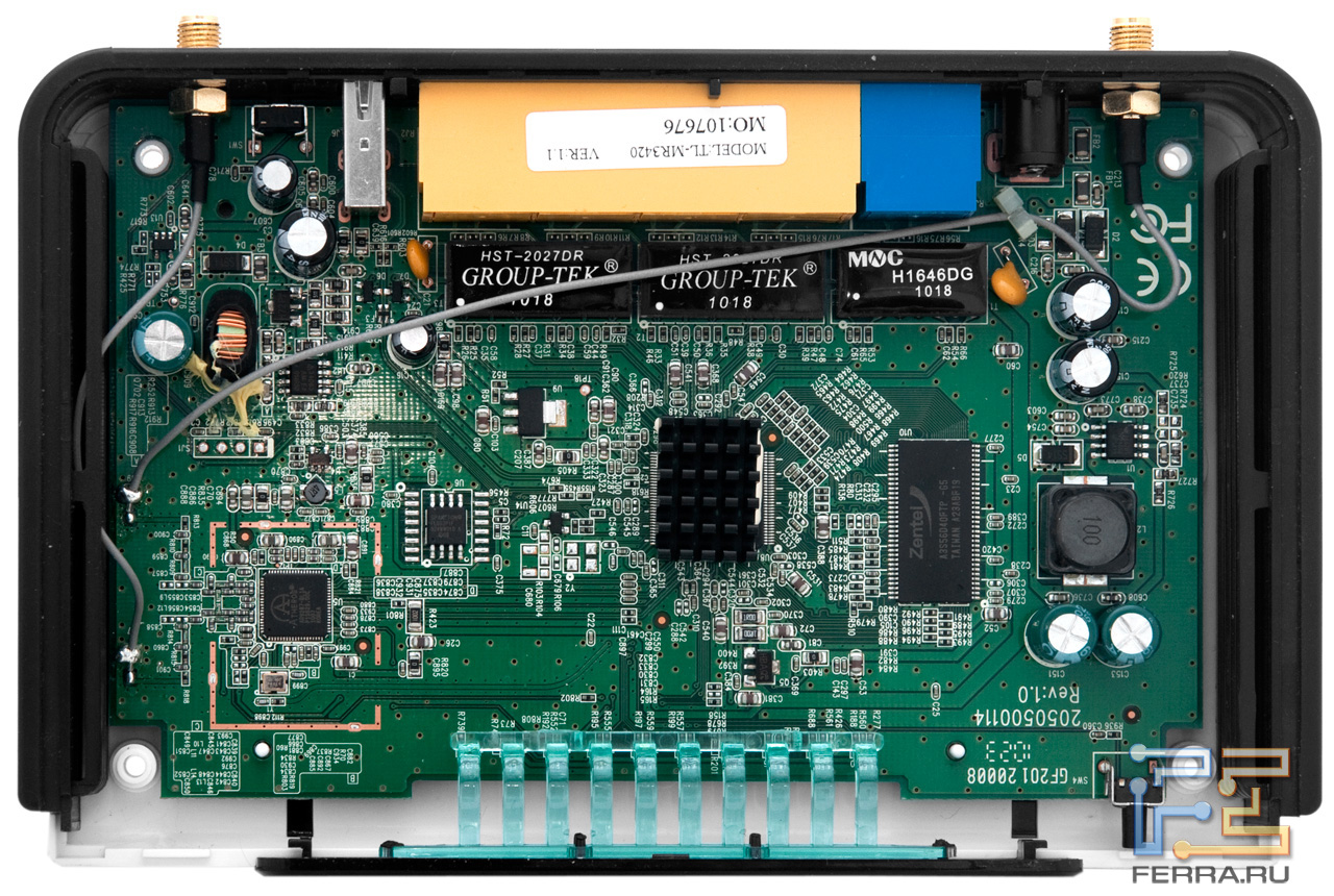
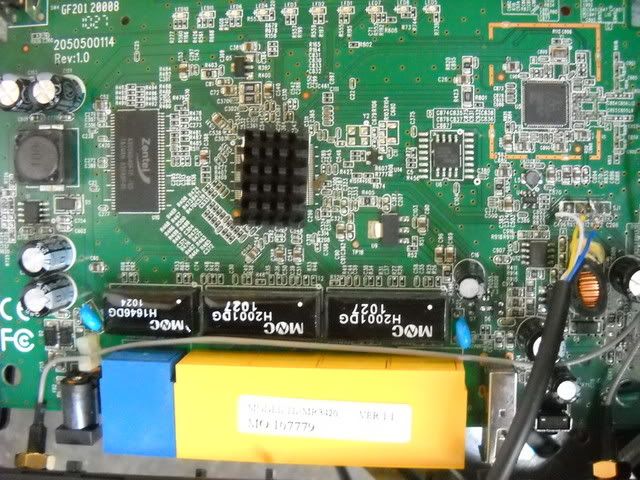
MR3420 v2.3
Board:

Serial
Pinout
Pinout for MR3220
| SJ1 | |||
|---|---|---|---|
| 1 | 2 | 3 | 4 |
| TX | RX | GND | VCC |
Pinout for MR3220 V2.2 (I have V2.3 as on photo with V2.2 on bottom) only
| JP1 | |||
|---|---|---|---|
| 1 | 2 | 3 | 4 |
| RX | TX | GND | VCC |

Pin 1 is clearly marked on the board.
To be able to use the UART on MR3220v2, TP18 to TP38 and TP28 to TP48 should be connected.
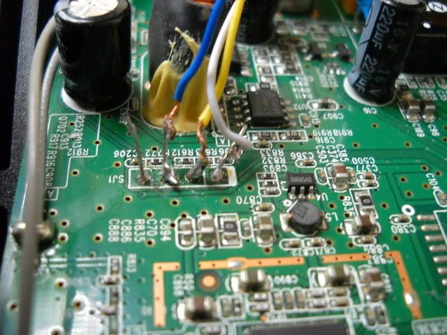
This is how I did mine:

Another one:

To get the serial connection work reliably, you have to connect a 10k pullup resistor between the TX and the 3.3V pin. This is because the TX pin is connected to a voltage divider (2×5.6k) and a capacitor is put between the real pin and the TX connector. 1)
Now connect a serial hack adapter (DKU-5, CA-42 or similar containing the PL-2303 chip) and away you go!
This adapter can be also used provided a serial port is present on the PC. Tested on MR3420 v2.2, but it requires a 4.7k pulldown resistor between Tx and GND. When using it, router has to be powered on, and after that connect the pulldown, Tx and Rx pins. (Tx from schematic goes to Tx pin of router, Rx from schematic to Rx of router).
The right settings for accessing the serial console are as follows:
Bits per second: 115200
Data bits: 8
Stop bits: 1
Parity: None
Flow control: None
Password to get into uboot prompt is tpl
Password to get root login is 5up
MR3420 v2.2 has all the signals routed to the pins so you don't have to solder any additional wires. See here http://blog.technicentral.com/index.php/2-routers/1-mr3420-unbrick
Basic configuration
Since this part is identical for all devices, see Basic configuration.
Note: (TP-Link MR3420 v1.2) In case the vlan switch configuration is not created automagically (⇐ 10.03.1) and there is eth0 and eth1 after bootup change /etc/config/network to reflect the vlan setup by adding the lines below. Also replace the 'option ifname “ethX”' accordingly (eth0.1, eth0.2). The proper ethernet port layout has still to be confimed.
config switch eth0
      	option reset 1
      	option enable_vlan 1

config switch_vlan
        option device eth0
        option vlan 1
        option ports "0t 1 2 3 4"

config switch_vlan
        option device eth0
      	option vlan 2
      	option ports "0t 5"
In MR3220 v1.2 is:
config 'switch'
	option 'name' 'eth0'
	option 'reset' '1'
	option 'enable_vlan' '1'

config 'switch_vlan'
	option 'device' 'eth0'
	option 'vlan' '1'
	option 'ports' '0 1 2 3 4'
OEM firmware features
Since this is the same for all TP-LINK products, see TP-LINK firmware features.
OEM source code available at:
for TL-MR3220 and TL-MR3420 V.1 - http://www.tp-link.com/resources/GPL/mr3420_3220v1.tar.gz,
for TL-MR3220 V.2 - http://www.tp-link.com/resources/gpl/150Router.rar,
for TL-MR3420 V.2 - http://www.tp-link.com/resources/gpl/ap123_gpl.tar.gz
Failsafe
Failsafe is a quite popular feature, of this router, thats lets you recover instantly from a misconfiguration above.
Use the QSS button instead of reset button, everything else is identical to generic failsafe document.
Failsafe may not work in Backfire before r29661, so it's confirmed to not work at Backfire 10.03.1 launch (r29592). Be extremely cautious on what you're doing or go directly to serial recovery.
Note for MR-3220 running on 12.09-rc1 (r34185): I did not get any UDP packets to port 4919 as promised either when connected to LAN or WAN, however repeatedly pushing the front button made the router to enter the failsafe mode, which allowed me to gain again access to the router. The problem almost bricking my router was in my network configuration, for some reason setting a fixed MAC address for a bridge caused the router to hang at /etc/init./network start.
FAILED SETTING SOLUTION (NOT THE FAILED FLASH!):
In case of failure or an installation package settings can sometimes cause the router cannot be accessed either administrator page (http://192.168.1.1) also through the console. This condition can be addressed in the following way;
1) turn off and turn on the Router 2) Shortly lights up press the SYS LED is that flashing LED SYS, will very quickly. 3) Now the Router has been accessible via TELNET 4 Router with TELNET) Login 5) type in the command: firstboot 6) type in the command:/etc/init.d/uhttpd start 7) went back to the Admin page in a browser with the address: http://192.168.1.1
Connect stuff to the USB port
To connect stuff to the USB port, please see Connect stuff to the USB port.
Turn USB power off
On a TL-MR3220 do like this:
- ON
echo 1 >/sys/class/gpio/gpio8/value
- OFF
echo 0 >/sys/class/gpio/gpio8/value
Hardware Mods
Deep MMC Hack
Unlike standard modding mmc_over_gpio - where was necessary to find 4 unused GPIOs, in the deep modding we can use only one GPIO(or two GPIOs if whe want to use SD card as hotplug SPI device), because we will use a common SPI bus with NOR flash memory.
Due to the fact that on routers MR3420/MR3220 V1.x we have limit of available unused GPIOs, we forced to use the common SPI bus with NOR flash memory (spi0.0) where MMC/SD memory card will be - spi0.1
How to do this is described in this link.