Linksys by Cisco WRT160NL
Atheros AP81 reference design with USB & 802.11 b/g/n WiFi.
Supported Versions
Hardware Highlights
Installation
→ Install OpenWrt (generic explanation)

| Seems to be fine with 10.03.1 - FLASHING WITHOUT SERIAL CONSOLE PER LINKSYS-WEBINTERFACE MAY WORK, USE AT OWN RISK (See Note3) ! |
Using ready build
You can download 10.03.1 build called openwrt-ar71xx-wrt160nl-squashfs-factory.bin. After using it you will have to install kmod-ath9k to get WiFi working...
opkg update; opkg install kmod-ath9k
rm -rf /etc/config/wireless; wifi detect > /etc/config/wireless
...and to add wpa encryption if you plan to use it.
Warning: If have some of those models, that belong to version 'CUR06', the 10.03 and 10.03.1 release of backfire WILL NOT work (kernel panic!), because of the newer u-Boot version (1.6.1). There were some changes of the memory layout. To get it working you must use the image from backfire trunk release by now!
Building OpenWrt yourself
People who want more up-to-date OpenWrt may build a copy of trunk with the WRT160NL profile selected.
OEM easy installation
Can be flashed from the original web interface with file openwrt-ar71xx-wrt160nl-squashfs.bin
OEM TFTP install
Set a PC on same network to some address in IP range 192.168.1.[2-254]. Download either Linksys or OpenWrt firmware image (openwrt-ar71xx-wrt160nl-squashfs-factory.bin), store as code.bin. From serial console abort the U-boot process. Enter this on u-boot command line
ar7100> upgrade code.bin
check link duplex:Full/speed:100
dup 1 speed 100
Tftpd start listening on port[69]!
Load address: 0×80060000
Send file from windows PC with TFTP:
C:\tmp> tftp -i 192.168.1.1 put code.bin
For linux TFTP
tftp -m binary 192.168.1.1 69
tftp> put code.bin
You should see this on console wait for flash to finish:
Receiving firmware [code.bin] from [192.168.1.10]
Write File : CODE.BIN
Once U-boot command prompt returns enter
ar7100 > go
Hint: The special “linksys-tftp” client that can be found in portage of Gentoo Linux seems not to work. Please use atftp if you're using Gentoo Linux or some other distribution that is based on portage:
root@host ~ $ atftp
> mode octet
> connect 192.168.1.1 69
> put code.bin
unbricking via tftp
This step has helped me to unbrick the router linuxbsd. You can try something like this (from a GNU/Linux computer):
1. Turn off the power to the router and leave it off until the final step.
2. Make sure your computer has a static IP address from 192.168.1.x (eg. 192.168.1.4)
3. Make sure the ethernet cable is plugged into one of router's LAN ports and the other end into computer's ethernet port
3. cd to the folder where you have the image
4. change the name of the new firmware to code.bin , then type :
5. echo -e "binary\nrexmt 1\ntimeout 60\ntrace\nput code.bin\n" | tftp 192.168.1.1
6. plug the power into the router, it should flash.
Upgrading OpenWrt
Sysupgrade
In trunk changeset 17202 sysupgrade got enabled for the WRT160NL. (There remains some question that this will JustWork. See ticket #8960 for details)
cd /tmp
wget ...
sysupgrade -n openwrt-ar71xx-wrt160nl-squashfs.bin
The sysupgrade -n command line switch tells sysupgrade to not keep the configuration files.
mtd
cd /tmp
wget ...
mtd -r write /tmp/openwrt-ar71xx-wrt160nl-squashfs.bin firmware
Migrate from DD-WRT to OpenWrt
cd /tmp
wget ...
mtd -r write /tmp/openwrt-ar71xx-wrt160nl-squashfs-factory.bin linux
Basic configuration
→ Basic configuration After flashing, proceed with this.
Set up your Internet connection, configure wireless, configure USB port, etc.
Support history
Hardware
Info
| Architecture | Atheros AP81 |
|---|---|
| Vendor | CyberTan |
| Bootloader | U-boot 1.1.5 / 1.1.6 |
| CPU | Atheros 9130-BC1E 400 MHz |
| Flash-Chip | cFeon EN25P64 8 MiB |
| RAM | Samsung K4H561638J-LCCC 32 MiB |
| Wireless | Atheros 9102 802.11 b/g/n (integrated) |
| antenna | 2 removable external RP-SMA dipoles |
| Ethernet | RTL8306SD |
| USB | Yes 1x 2.0 |
| Serial | Yes |
| JTAG | Yes |
Photos
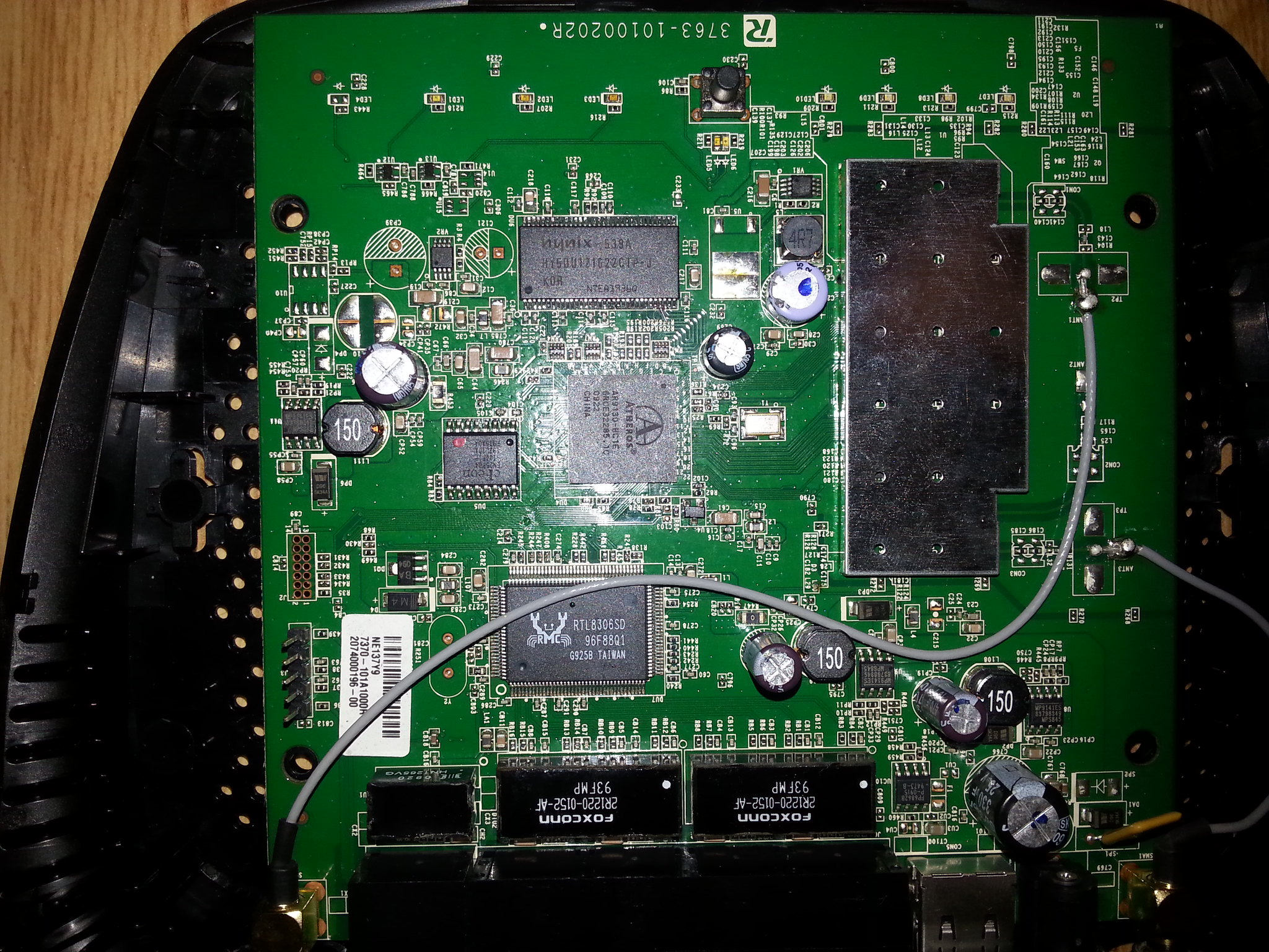
Annotated photos available here
Model Number
Opening the case
Note: This will void your warranty!
- To remove the cover simply unscrew and remove the antennas, remove the 4 phillips-type screws on the bottom, and pry the case apart.
- There are no screws holding the PCB to the bottom cover once open.
Serial
Typical 3.3 volt TTL serial console present in 3 locations. The parameters are 115200 8-N-1
Location J3 on PCB with pin-header installed:
| pin | function |
|---|---|
| 1 | 3.3V |
| 2 | TX |
| 3 | RX |
| 4 | NC |
| 5 | GND |
Initial successful efforts used a short Nokia DKU-5/CA-42 cable, these Atheros platforms seem to be difficult to work with using FTDI long cables.See Serial Consolefor more details. EDIT - If you don't want to short your cable, use an old lynksys non-switching power adapter with transformer (switching adapters are generating noise which breaking serial console comunication)
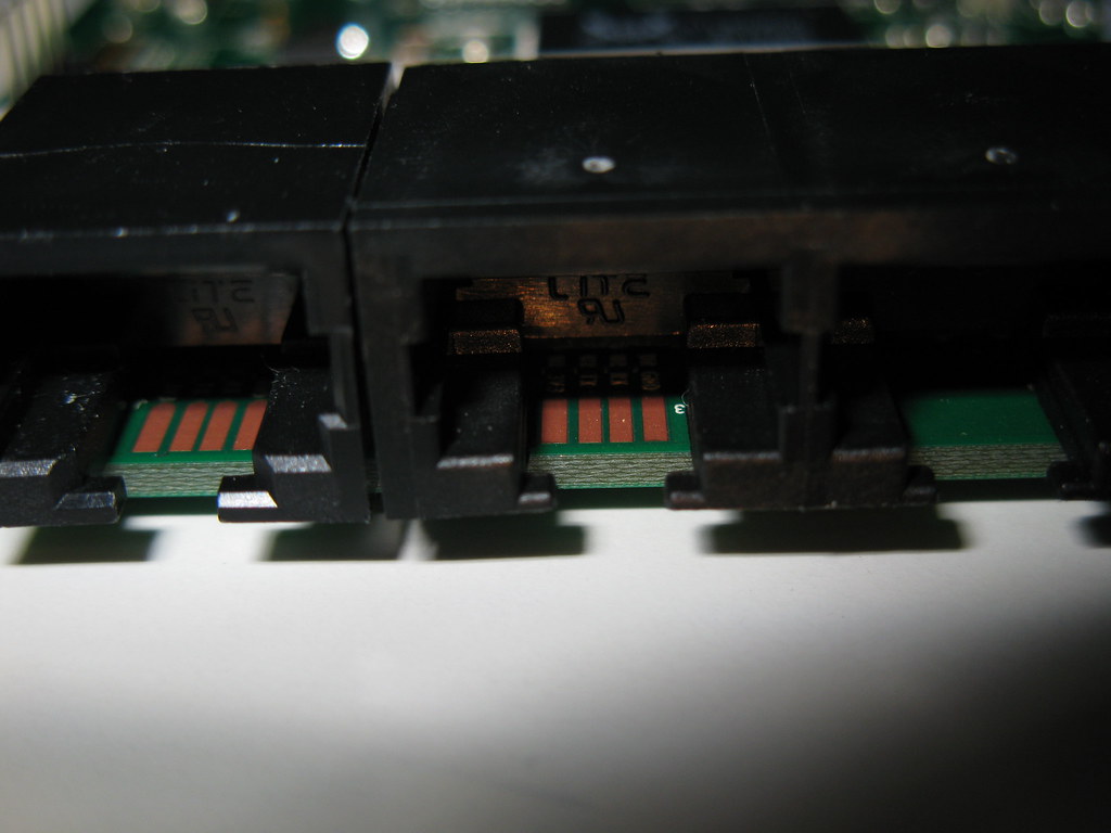
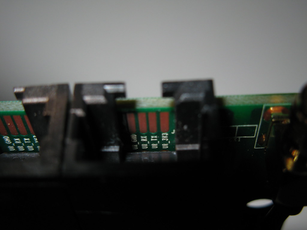
There are duplicate serial console contact points inside WAN & LAN4 ports on PCB edge. You can modify an RJ45 plug with wires in the appropriate spots to access serial console without cracking open the case. Here is an example crafted by users retracile and EraZor:
JTAG
There is a micro-JTAG connector present.
The programmer needed to access the SPI flash through the Jtag points is a USBJTAG NT from http://www.usbjtag.com/.
The JTAG should be 2mm spacing. IR length 5 The pinout is the same as regular 14 pin JTAG.
To read the flash you need to send a poke command bf000000,1 (using TJTAG) not needed in NT software as it is already implemented. Programming can only be done by USBJTAG NT for now.
http://www.usbjtag.com/jtagnt/router/wrt160nl.php shows a rough connection to Jtag points. More information can be found on the USBJTAG forums.
GPIO
| pin | function |
|---|---|
| 6 | LED_WLAN |
| 7 | BTN_WPS |
| 8 | LED_WPS_BLUE |
| 9 | LED_WPS_AMBER |
| 14 | LED_POWER |
| 21 | BTN_RESET |
As reported here
and here (in Polish)
http://openrouter.info/forum/viewtopic.php?f=19&t=554
and here
http://www.instructables.com/id/How-to-set-up-home-data-server-using-OpenWRT-on-Li/
there are two easily accessible spare gpios. Gpio13 is the RX pin on the serial header (so you can't use it at the same time as the serial port obviously), and gpio0 is at the bottom left of the board, where there are pads for a fourth LED which has not been soldered in. The author of the first link above reported that gpio13 would only work as an output, not as an input. I did not have that problem.
Adaptive Noise Immunity (ANI) latency issue with WIFI
Also reported on other products with the same chipset like TP-Link TL-WR1043ND and others, see https://dev.openwrt.org/ticket/12372
The WIFI chipset in the WRT160NL features a technology called Adaptive Noise Immunity (ANI), that is meant to help operation in noisy environments. The system implements a noise filter and should converge to the set of parameters that guarantees the best possible throughput for the given environment and trace changes in the environment. Unfortunately, the ANI implementation in the ath9k driver is buggy (at least up to the Linux kernel in Chaos Calmer). As a consequence, in certain environments rather than helping throughput ANI ends up deteriorating performance in an horrible way. In some conditions, rather than converging to the best possible parameter set, the ANI control system starts showing instability (oscillations through different sets of parameters) or even divergence towards some extreme and unsuitable parameter sets.
The issue is subtle, as it may not manifest at all in some environments. In other cases, it may take days for the issue to show up. In other cases, the system may encounter the issue, recover by itself and work fine for some time, show the issue again, etc… Most users who experience the issue, encounter it every few hours or on a daily basis.
A quick list of signs that you are encountering the issues are:
1. Huge ping time from the wrt160nl to another system linked to it via WIFI and very close to it (e.g. ping times in the order of some thousands milliseconds). 2. Strong jitter in the ping times, with long and short return times alternating (e.g. 1.0ms 0.9ms 60ms 0.9ms 1.1ms 40ms 1.0ms 33ms 0.9ms 0.8ms 70ms ...)
3. The disappearing of 1. and 2. when the wifi interface is restarted (e.g. by issuing the wifi command at the shell prompt)
The obvious workaround for the issue is to disable ANI altogether. For testing purposes this can be done in such a way that will not survive a reboot. In Chaos Calmer, issue
echo 0 > /sys/kernel/debug/ieee80211/phy0/ath9k/ani
in previous releases you may need
echo 1 > /sys/kernel/debug/ieee80211/phy0/ath9k/disable_ani
Once you are sure that the fix works for you, it is possible to make it permanent by placing the previous code in the /etc/rc.local file.
Specific configuration
Interfaces
The default network configuration is:
| Interface Name | Description | Default configuration |
|---|---|---|
| br-lan | LAN & WiFi | 192.168.1.1/24 |
| eth0 | LAN ports (1 to 4) | None |
| eth1 | WAN port | DHCP |
| wlan0 | WiFi | Disabled |
Switch Ports (for VLANs)
| External Label | Port |
|---|---|
| 1 | 3 |
| 2 | 2 |
| 3 | 1 |
| 4 | 0 |
Port 4 is the internal/cpu port. Port 5 (tagged 'CPU' in LUCI) is probably unconnected.
Note that, at least for 12.09, switch support seems to have issues: switch configuration changes don't “take” until a reboot, and when configuring tagged and untagged VLANs, outgoing traffic for the untagged VLAN is still tagged. This needs to be further investigated.
If you don't need the switch, consider swapping the WAN and LAN ports as eth1 is directly connected.
Failsafe mode
If you forgot your password, broken one of the startup scripts, firewalled yourself or corrupted the JFFS2 partition, you can get back in by using OpenWrt's failsafe mode.
Boot into failsafe mode
- Unplug the router's power cord.
- Connect the router's LAN1 port directly to your PC.
- Configure your PC with a static IP address between 192.168.1.2 and 192.168.1.254. E. g. 192.168.1.2 (gateway and DNS is not required).
- Plug the power on and wait for the DMZ LED to light up.
- While the DMZ LED is on immediately press any button (Reset and Secure Easy Setup will work) a few times .
- If done right the DMZ LED will quickly flash 3 times every second.
- In some cases the WPS LED will flash nonstop very rapidly when it goes into failsafe mode.
- You should be able to telnet to the router at 192.168.1.1 now (no username and password)
- Be persistent, sometimes it takes a few tries, if it doesn't work the first time, keep trying.
What to do in failsafe mode?
NOTE: The root file system in failsafe mode is the SquashFS partition mounted in readonly mode. To switch to the normal writable root file system run mount_root and make any changes. Run mount_root now.
1. Forgot/lost your password and you like to set a new one
passwd
2. Forgot the routers IP address
uci get network.lan.ipaddr
3. You accidentally run 'ipkg upgrade' or filled up the flash by installing to big packages (clean the JFFS2 partition and start over)
mtd -r erase rootfs_data
If you are done with failsafe mode power cycle the router and boot in normal mode.
Buttons
There are 2 buttons. They are Reset and WiFi Protected Setup. The buttons can be used with hotplug events. E. g. [#wifitoggle WiFi toggle].
| BUTTON | Event |
|---|---|
| Reset | reset |
| WiFi Protected Setup | wps |
Antenna
The supplied short dipole antennas can be easily replaced with large omni or directional antenna.
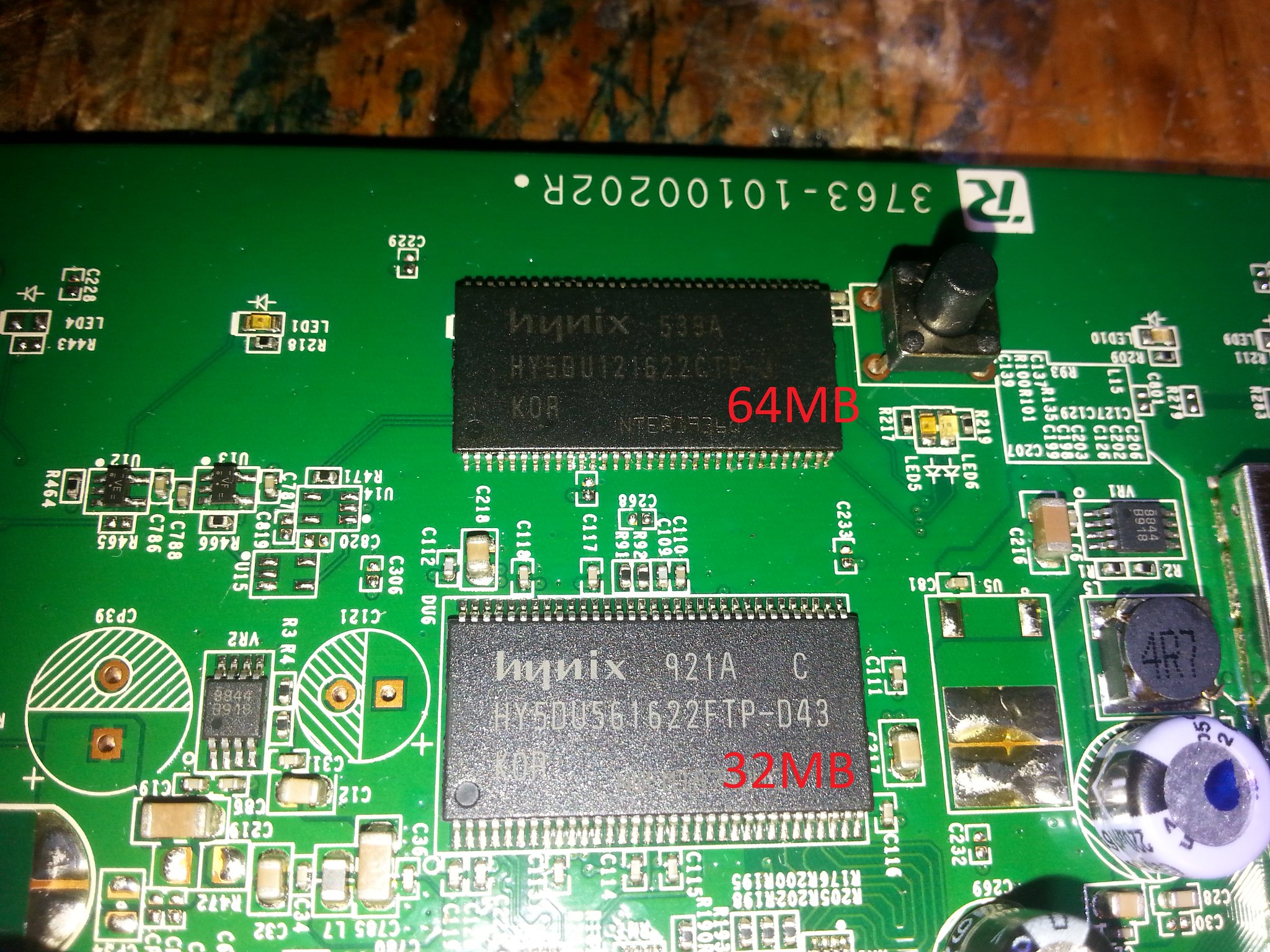
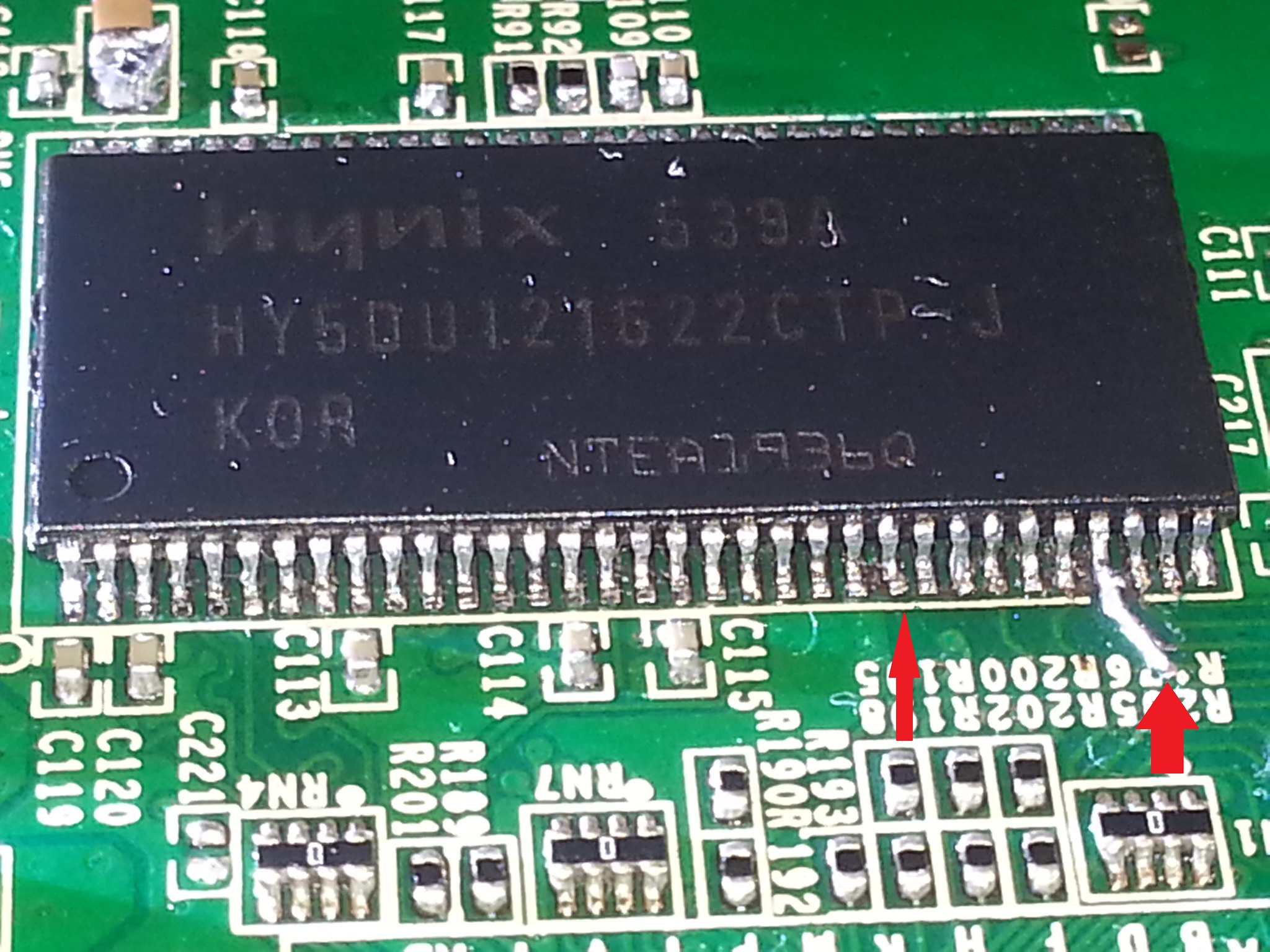
RAM mod 64mb
It is possibile to gain 64MB ram by replacing ram chip
beare loosed pins, they can be tricky to repair.
Other info
- Original exploration thread https://forum.openwrt.org/viewtopic.php?id=20298&p=1


