PC Engines APU 4
These boards are essentially the same as the PC Engines APU2 and PC Engines APU3 but with 4 Ethernet ports and no straddle mount PCIe x 1 port (which the apu3 has) and almost everything which applies to the apu2/3 also applies to the apu4, and vice versa.
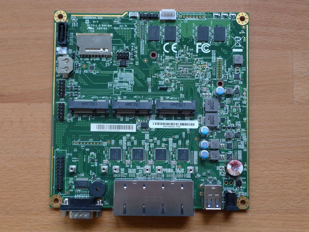
Apu4 boards have 3 mPCIe slots with the same configuration as the apu3 - the first is wired for mSATA, USB and a SIM and is intended to be used for a mPCIe SATA drive or an LTE modem, the second has USB and a SIM connection only, also intended to be used with an LTE modem and the final mini PCIe socket has PCIe and USB but no SIM connection and is intended for a WiFi card.There is also an onboard SATA port in addition to the mSATA port. There is also an sd card slot which is bootable. The board can boot from usb, sata, sdxc, or pxe boot.
At least some 5G m.2 modems will work with a Mini PCIE extender and a Mini PCIE to M.2 B key adapter (make sure you get one which connects the PCIe bus). However as only one Mini PCIe socket actually has a PCIe bus connected you cannot install a 5G modem and a WiFi card - the apu2 would be the variant to use for this application as two of its Mini PCIe sockets have the PCIe bus connected.
Unfortunately the GX-412TC has been out of production since the summer of 2023, PC Engines acquired enough stock to continue manufacturing until June 2024 but after this date no more boards have been manufactured. At the time of writing (April 2025) there may be some limited new stock of the apu4 in retail outlets.
Hardware variants and features
There are two basic variants as with apu2/3 - a base model with 2GB DDR3-1333 (soldered) and a 4GB model, the latter has ECC memory, all have the AMD GX-412TC 1GHz SOC; as of bios version 4.9.02 a turbo boost up to 1.4GHz can be enabled in the bios settings.
The final digit of the part number denotes the RAM size, the preceding letter the board revision (this is the same throughout the apu2/3/4/6 series) - the two most recent versions being the apu4d2 and apu4d4 - there is also a “b” and “c” revision - changes between these and the “d” can be found on the product web page
- CPU: AMD Embedded G series GX-412TC, 1 GHz quad Jaguar core with 64 bit and AES-NI support, 32K data + 32K instruction cache per core, shared 2MB L2 cache.
- DRAM: 2 or 4 GB DDR3-1333 DRAM
- Storage: Boot from SD card (internal sdhci controller), external USB or m-SATA SSD. 1 SATA + power connector. mSATA is shared with miniPCI express.
- 12V DC, about 6 to 12W depending on CPU load. Jack = 2.5 mm, center positive
- Connectivity: 4 Gigabit Ethernet channels (Intel i211AT)
- I/O: DB9 serial port, 2 USB 3.0 external + 2 USB 2.0 internal, three front panel LEDs, pushbutton
- Expansion: 3 miniPCI express (J13 USB or mSATA, apu4*4: with SIM; J14 USB only, with SIM; J15: full miniPCI express, but no SIM, intended for wifi). GPIO header, optional I2C bus, COM2 (3.3V RXD / TXD).
- Board size: 6 x 6“ (152.4 x 152.4 mm) - same as apu1d, alix2d13 and wrap1e.
- Firmware: coreboot
- Cooling: Conductive cooling from the CPU to the enclosure using a 3 mm alu heat spreader (included).
Supported Versions
Hardware Highlights
Installation
Installation is straightforward - follow the generic x86 instructions to download or create a bootable USB, mSATA or SD drive with the OpenWrt image and install it on the apu - note that the Intel i211AT drivers are not included in the stock x86 images and will need to be copied onto the boot media separately and then installed with opkg - you need the kmod-igb package.
Other useful modules and packages are the same as on the PC Engines APU2 boards
| Module/Package | feature(s) | menuconfig location |
|---|---|---|
| kmod-igb | Intel NIC drivers | Kernel modules/Network Devices |
| kmod-pcengines-apuv2 | APU2 front LED & button control | Kernel modules/Other modules |
| kmod-gpio-amd-fch | AMD Fusion Hub Controller | Kernel modules/GPIO support |
| kmod-crypto-hw-ccp | AMD Cryptographic Coprocessor | Kernel modules/Cryptographic API modules |
| kmod-gpio-nct5104d, kmod-gpio-button-hotplug | GPIO pins or COM2/3/4 | Kernel modules/Other modules |
| kmod-sp5100-tco | Hardware watchdog | Kernel modules/Other modules |
| kmod-usb-core, kmod-usb-ehci, kmod-usb-ohci, kmod-usb2, kmod-usb3 | USB v2 and v3.0 support | Kernel modules/USB Support |
| kmod-sound-core, kmod-pcspkr | Onboard PC speaker | Kernel modules/Sound support |
| amd64-microcode | AMD CPU microcode | Firmware |
| irqbalance | IRQ usage balancing for multi-core systems | Utilities |
| fstrim | discard unused blocks on SSDs | Utilities/Filesystem |
Remember to edit the kernel command line to include console=ttyS0,115200,n8
Dual boot systems are also relatively easy to create - install your desired Linux distribution then use the separate kernel and root filesystem images for the x86 target to configure grub to load OpenWrt.
Schematics, datasheets and firmware information
- NIC Datasheet: i211AT
- NCT5104D GPIO Datasheet | https://pcengines.ch/file/NCT5104D_Datasheet_V1_9.pdf |
- Open source code and additional documentation https://github.com/pcengines
Debricking
Firmware for the board is available here, flashing is fairly straightforward (see BIOS Update instructions of PC Engines APU1, APU2 and APU3) but the lack of /dev/mem in the stock OpenWRT images means that it is not possible to use them for flashing firmware - either the custom image with /dev/mem can be used or use a “live” or “rescue” image from another Linux distribution (eg Fedora). You will probably need to check which SPI flash chip is on the board (e.g. the W25Q64JVSSIQ) so the command to flash a new firmware image, once you have assembled all the parts will be something like:
# flashrom -c “W25Q64JV-.Q” -w apu4_v4.19.0.1.rom -p internal
If you do manage to brick the device it is possible to use a small external board to override the motherboard flash chip - see https://www.pcengines.ch/spi1a.htm though you might have to build one from the schematic.
Network interfaces
As with the APU2 in the default configuration eth0 is the one closest to the serial port.
The default network configuration is:
| Interface Name | Description | Default configuration |
|---|---|---|
| br-lan | LAN (eth1 - eth3) | 192.168.1.1/24 |
| wan | IPv4 WAN connection (eth0) | DHCP client |
| wan6 | IPv6 WAN connection (eth0) | DHCPv6 client |
Buttons
A power and a reset button can be connected to the J3 header and work as you would expect.
Behind the “front” of the unit there is a single button (labelled SW1 on the schematic). With the kmod-pcengines-apuv2 and kmod-gpio-button-hotplug modules loaded it will generate reset button events.
Additionally the NCT5104D GPIO chip can be used to connect buttons and generate events.
Ports and connectors
See page 9 and 10 of the user manual for a list of the internal connectors (reproduced below)
| Connector | Function | Notes |
|---|---|---|
| BAT1 | Battery | LR44 1.5V alkaline battery for RTC / CMOS |
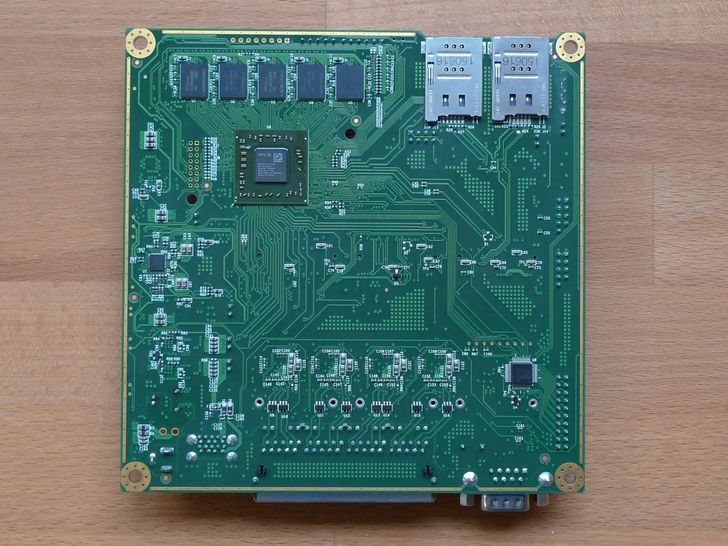
| J1 | SIM | (bottom side) – SIM socket for 3G modem installed in miniPCIe J14. Can be swapped with J2 SIM under software control (no SIM switch on apu4c2). |
| J2 | SIM | (bottom side) – SIM socket for 3G modem installed in miniPCIe J13. Can be swapped with J1 SIM under software control (not installed on apu4c2). |
| J3 | Power/Reset | Pins 1-2 = reserved (BIOS write protect) Pins 2-3 = power button Pins 4-5 = reset button Pins 5-6 = reserved (watchdog enable) |
| J4 | COM2 | 3.3V serial port (RXD / TXD only). |
| J5 | I2C / LED | optional expansion, see schematic for pinout |
| J6 | SATA | Sata drive connector |
| J7 | SATA pwr | 5V power for SATA drive |
| J8 | SD card | SD card interface, driven by AMD SOC, use sdhci driver. |
| J9 | SPI | SPI header for debricking. Do not connect pins 7 / 8 for Dediprog use |
| J10 | CMOS reset | Short these pins while power is off to clear RTC / CMOS RAM. Don’t leave jumper permanently as this would drain the battery. |
| J11 | JTAG | Unpopulated |
| J12 | USN | Internal USB (2 x USB 2.0) – present on apu4c and later. |
| J13 | Mini PCIe/mSATA | This slot can be used for mSATA SSD, or 3G/LTE modem (USB based). No PCI express = no wifi. Connects to SIM J2 |
| J14 | Mini PCIe | This slot can be used for 3G/LTE modems (USB based). No PCI express = no wifi. Connects to SIM J1 |
| J15 | Mini PCIe | This slot includes PCI express, and is intended for wifi modules. No SIM connected |
| J16 | USB | Internal USB (2 x USB 2.0)nternal USB (2 x USB 2.0) |
| J18 | GPIO | General purpose I/O pins + extra serial ports, driven by Nuvoton NCT5104D I/O controller. Data sheet and sample code available on request |
| J19 | Power | Optional power header, designed for 0.156” pitch header (Digi-Key part A1971-ND) |
| J20 | COM1 | RS232 Serial port with full handshake signals |
| J21 | USB | External USB (2 x USB 3.0) |
| J22 | Power | DC jack (2.5 mm center pin, center positive) |
| J23 | LAN 1-4 | GigE port. Left LED (green) indicates activity, right LED (amber) is turned on when the connection is Gigabit |
| J24 | LPC | Minimal LPC header for debug and TPM (apu4c and later). |
Serial
There are two port.serial Serial ports. COM1 on the external DB9 connector (J20) is RS232 levels with full handshaking, there is also an internal 3.3V TTL level port COM2 which just has transmit/receive data with nbo handshaking.
An additional two serial ports can be configured using GPIO pins.
Default parameters for COM1: 115200, 8bit, no parity.
JTAG
There is an unpopulated port.jtag JTAG port (J11), no information is given about this though the connections are shown on sheet 5 of the schematic (labelled AMD embedded probe header)
Given that the on board SPI flash can be overridden by an external flash chip it is unlikely that the JTAG port would be needed, even to restore a bricked device.
Info
Photos
Front:
Insert photo of front of the casing
Back:
Insert photo of back of the casing
Backside label:
Insert photo of backside label
Opening the case
when ordering this SBC you can choose to have it pre-assembled or not
disassembly and assembly instructions are available on the pcengines support docs
https://www.pcengines.ch/apucool.htm
THE CASE IS REQUIRED FOR CPU COOLING
POWERING UP THIS BOARD WITHOUT THE CASE BOTTEM CAN DAMAGE YOUR CPU
the case is aluminum and available in 3 colors:
black https://www.pcengines.ch/case1d4blku.htm
red https://www.pcengines.ch/case1d4redu.htm
blue https://www.pcengines.ch/case1d4bluu.htm
Main PCB:


