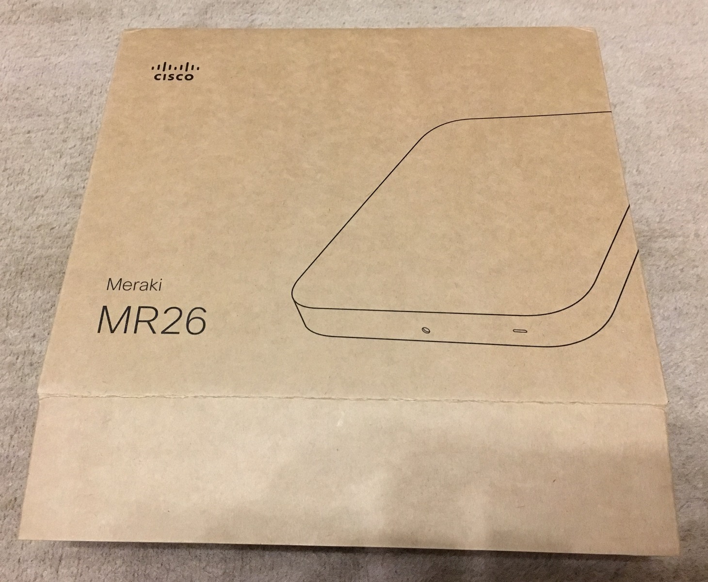
Meraki MR26
General availability: END of Sale was March 21, 2016.
Supported Versions: Not implemented (since August 29, 2018)
More information here: https://forum.openwrt.org/t/support-for-meraki-mr26/20142
Summary
Meraki MR26 is a wireless access point with the following features:
- cloud managed
- 3×3 MIMO 802.11n, dual-radio 802.11n, up to 900 Mbps
- 2.4 + 5 GHz dual band, triple radio (third one dedicated to scanning and rogue AP detection)
- Gigabit Ethernet port
- powered via 802.3af PoE or AC adapter
Hardware
- BCM53015A1KFEBG, Broadcom BCM53015 with with dual-core Cortex-A9 CPU at 800 MHz, 256KB L2 cache, 16-bit DDR2 interface, USB3, integrated switch, GPHYs and packet accelerator
- S34ML01G100TF100, S34ML01G1 1 Gb Spansion SLC NAND Flash Memory for Embedded, 1-bit ECC, x8 and x16 I/O, 3V VCC
- H5TQ1G63EFR, SK hynix Inc. 1Gb DDR3 SDRAM
- 2x BCM43431KMLG, BCM43431 802.11n baseband processor
- 24C64, 64 Kbit serial I²C bus EEPROM
- TPS23754, High Power/High Efficiency PoE Interface and DC/DC Controller
- NU801, 3 channel 16 bit PWM Constant Current Driver
- Optional Power Adapter: 12v, 1.5A, center positive.
Pictures
Opening the device is pretty straightforward:
- Remove the 4 rubber feet with a small flat-head screw-driver. They are just stickers over the screws.
- Use a small Philips screwdriver to remove 4 screws
- There are 5 plastic tabs (2 on each long side) that need to be pried apart with the flat screw driver or a shim, like a credit card (see the picture). Go slowly!
- There is no need to remove the gray plastic cover, but remove the six small screws along the side of the internals (see the picture).
- Carefully remove the circuit board cover.
- Inside are 3 VERY TIGHT screws that need to be removed to completely pull the circuit board out. They are very easy to strip. Not sure you need to remove them.
Pictures taken from a unit delivered in December 2015.
Serial Access
4 TTL connector pins are as follows (from top of picture going down toward AC port):
- VCC
- RX
- TX
- GND
Serial Port Settings: 115200, 8N1, Xon/Xoff


