Table of Contents
TP-Link TD-W9980 / TD-W9980B
The TD-W9980 is a VDSL-capable router launched in 2014. It's identical to the TD-W8980, so check that page out as some information is there and some here. The device works very well with OpenWrt, including the integrated DSL modem. Just the 5 GHz Wifi cannot be used and for VDSL you'll need to use a propriertary binary blob as described in this article.
This page is also for TD-W9980B which is nearly identical, with the exception that you can't flash via the Web UI exploit.
 The B is for annex B and cannot be changed. Check if your provider use this annex
OEM source code available at: GPL_TD-W9980.tar.gz
Supported Versions
Known Issues
- Switch acts weird (forwarding broadcast frames to all ports) ticket 14439 ticket 15511 can be fixed this way disable SW_ROUTING
- Switch doesn't allow tagged and untagged traffic on the same port, can be fixed with with Martin Schiller's changes
- Failsafe-Mode is not accessible via ethernet when triggered with the WPS button and indicated by led. (fixed for TDW8970)
Hardware Highlights
Installation
Device is not supported/built sysupgrade for yet, possible profile (plus fix for failsafe) can be found here.Seems like the W8980 image can by sysupgraded without an issue.
→ Install OpenWrt (generic explanation)
 Please add the installation procedure here.
Install OpenWrt via Serial Interface
This installation method works for all firmware versions of all devices that are mentioned on this page. However, it is necessary to open the case and to solder a pin header to prepare the installation.
How to open the case
Note: This may void your warranty
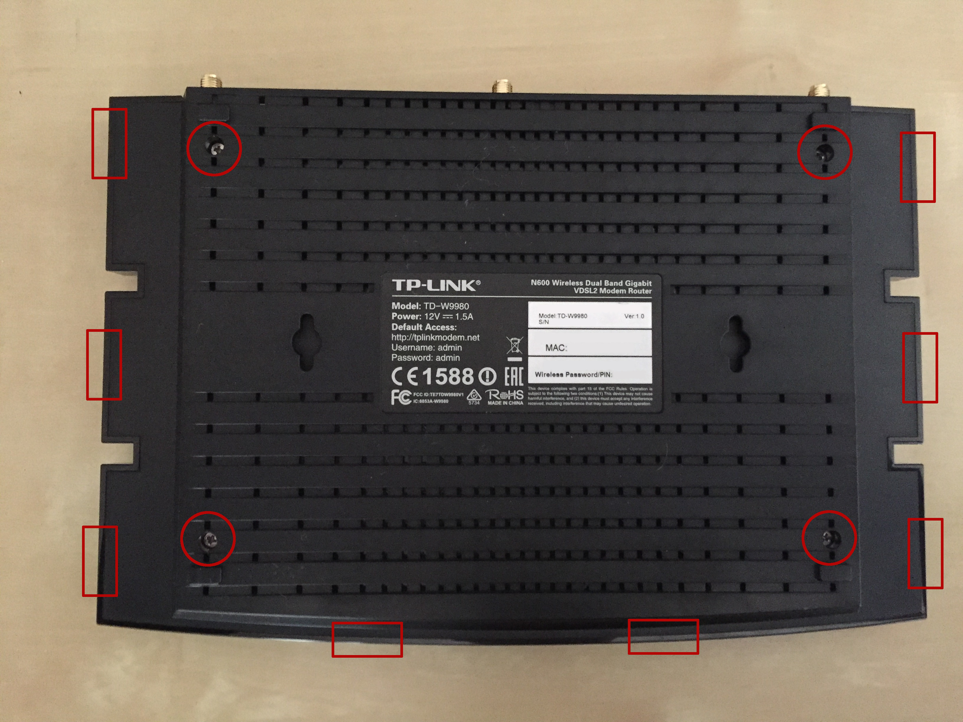
This case is pretty easy to open. First remove the four screws, and then pry the case with a small flat screwdriver, starting from the top (as that's the only non-tight place where you can actually put something) till the eight marked points of the case pop out.
Then you need to detach the U.FL RF connectors and make sure they're not in the way for pulling the board out. On W9980B one of them is hidden between tho components (one of them is a big red one). Gently push away the red one and pull the cable out.
Because there's copper pads on each side of the board which are glued to the plastic case while also being soldered onto the board, you're going to have to keep them attached for convenience and keep them in mind when manipulating with the board.
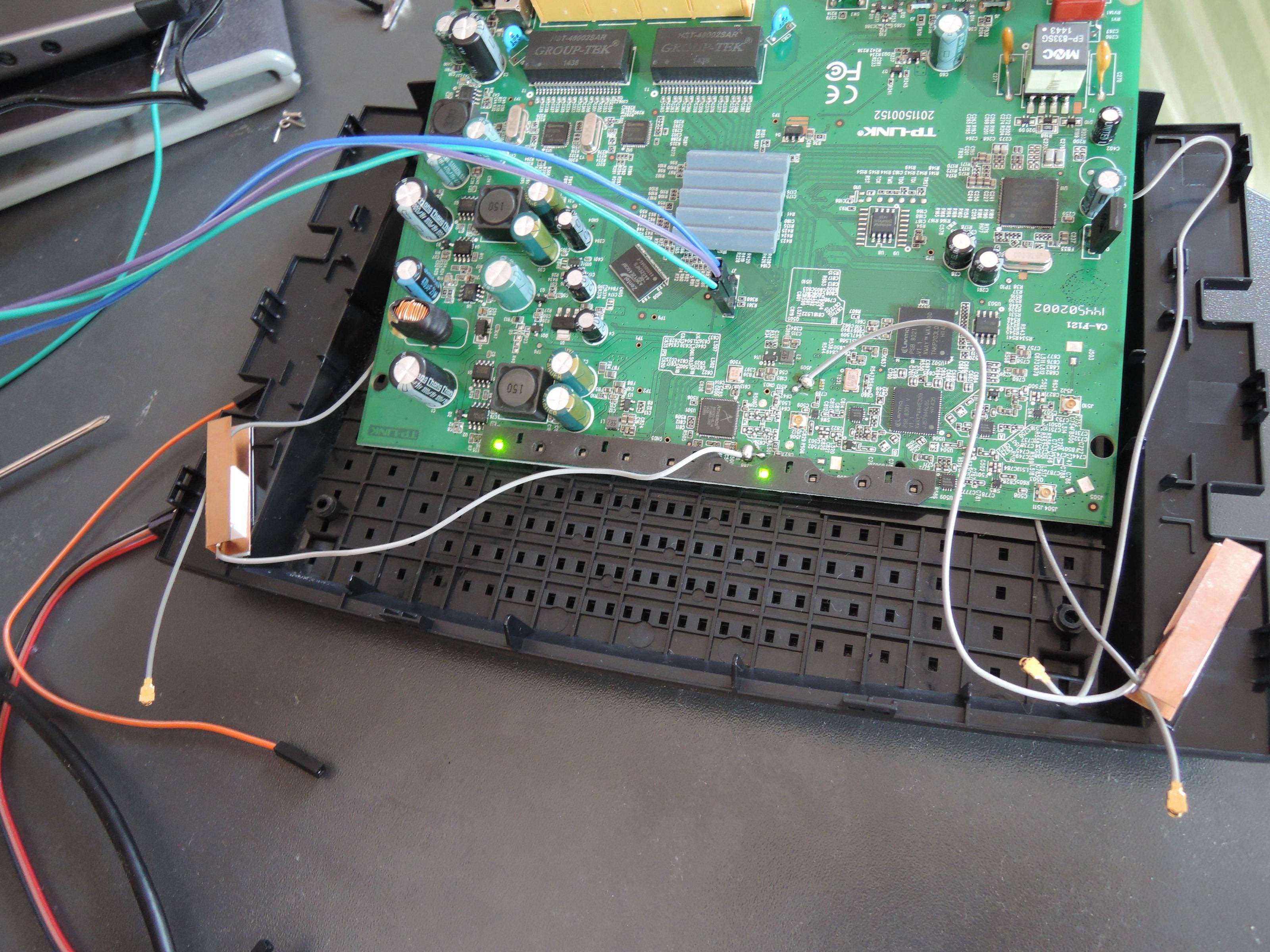
The UART is not populated, so you're going to have to solder a header on it. Look into the serial console informations at the start of the page for pinout for UART.
Serial Console Informations
The pin header for the serial console is not populated. It has to be soldered onto the board. A usual 2.5mm J7 pin header will do the job.

| Connector | J7 |
| Pins for TD-W9980B (from top to bottom) | Rx, Tx, GND, VCC (3.3V) DO NOT CONNECT VCC! |
| Serial connection parameters for TD-W9980 | 115200, 8N1 |
|---|
Press t on the console to interrupt U-Boot autobooting.
Logon through serial by pressing Enter and using: admin/1234.
Flashing
Provide Firmware via TFTP Server
Before starting the process, it is a good ideal to start a TFTP server on your PC listening on its Ethernet interface on IP 192.168.1.2/24. The default TFTP server IP for the u-boot that will be downloaded in the next step.
Download the 18.06.1 image file (openwrt-18.06.1-lantiq-xrx200-tplink_tdw8980-squashfs-sysupgrade.bin) and save it within the TFTP server's directory.
For ease connect the ethernet cable to the router and PC before starting the boot process.
Flash Bootloader
Firstly download bootloader file: u-boot.asc.
Connect a computer to the router via the UART (be careful not to fry the router with 5 Volts and use a logic converter to drop it down to the router's 3 Volt TX and RX pins). DO NOT CONNECT VCC!
Start 'screen', 'minicom' or similar serial console software.
Note: Make sure it accepts user input by interrupting normal booting by pressing 't' on U-Boot loading. If it doesn't, try another software. (screen recommended)
Left R225 pad, bottom of the board:

You need to keep a left side of R225 shorted to UART GND from boot to finishing of uploading the U-Boot image. A soldered cable will work, but an alligator clip connected to the GND on the UART and a small flathead screw driver or scissors pressed against the pad (shown in the image below) work as well, as long as you can hold them steady for about 30 seconds.
(The image above works for W9980 and W9980B, but is reportedly different for the very similar model w8980)
How the setup you end up with may look like (I opted for the scissors as the R225 pad is really tiny and I didn't have a proper soldering iron for that):
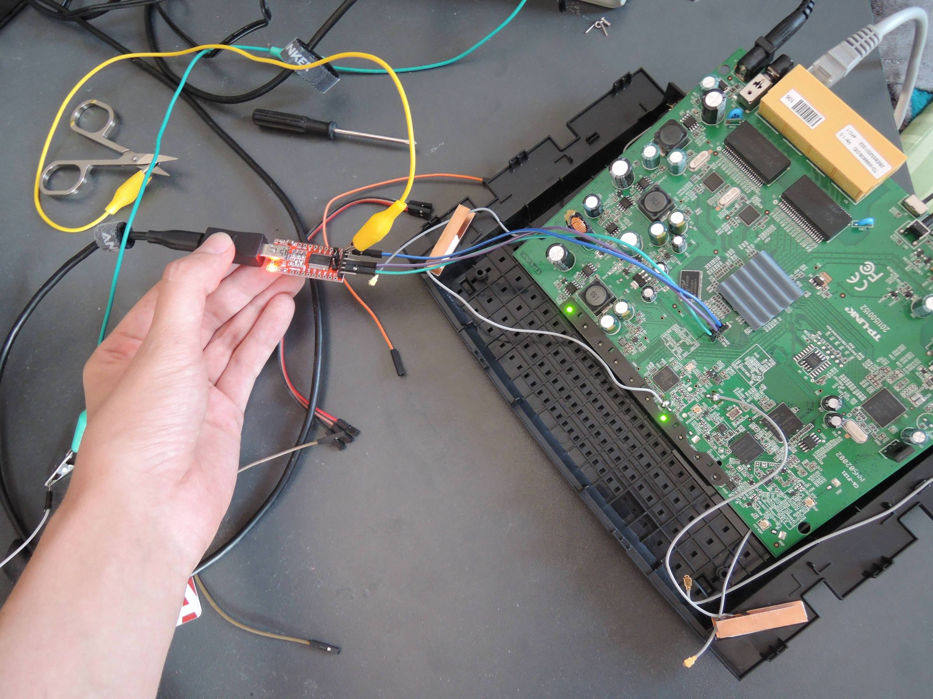
So, short the pin, power on the router and you should see a message similar to this:
ROM VER: 1.1.4
CFG 04
EEPROM Data OK
UART
Upload the U-Boot Image from another terminal via:
# cat u-boot.asc > /dev/ttyUSB0
Watch the loading progress via the console and wait a few minutes until it boots the U-Boot file.
Interrupt booting by pressing “t” key several times.
Disconnect the R225 pin from GND. Though you can keep it there until the flashing is done.
Flash Firmware
Now we need to upload the new firmware via tftp and erase the OEM firmware via the following commands:
tftp $(loadaddr) openwrt-18.06.1-lantiq-xrx200-tplink_tdw8980-squashfs-sysupgrade.bin
# Note: If you get timeouts (T) executing this command, you probably did not set up the networking/tftpd correctly or your ethernet cable is bad.
sf erase 0x20000 0x7a0000
sf write $(loadaddr) 0x20000 0x$(filesize)
reset
Allow the router to boot normally by rebooting it. You can now SSH into OpenWrt and start configuring the router. If a release version was flashed, the web configuration should be available now, too.
Install OpenWrt via Web Interface Hack (without opening the case)
TD-W9980 only, the B version supposedly uses a different encryption format the StatPOSTer tool can't deal with. Also note that the instructions in this section are written for 15.05 and W8970 image is used, but 18.06 is already out and W8980 may be a better fit.
This hack comes from member ejs on Kitz Forum. In this post, a description and link to required software is given.
The configuration (which is essential) is hidden (you need to become forum member), so I've added it here for ease of use.
Alternative to STATPoster is https://github.com/sta-c0000/tpconf_bin_xml
Requirements
- StatPOSTer-20160306.jar (A tool written in Java to create a manipulated router config-file)
- Java 8 (OpenJDK is fine) (Required to run the above file - newer versions don't seem to work)
- 9980-config-public-plus-shell.xml (Save as file, needed by StatPOSTer-20160306.jar to create the .bin config-file)
- OpenWrt TD-W8970 firmware for CC 15.05.1 (because there is nothing better matching available)
- OpenWrt TD-W8980 firmware, 18.06.5 (Newer version, also works fine)
- A Unix-like OS, capable of the dd command (the bash of Windows 10 Linux subsystem is fine also)
- An USB stick
Prerequisites
- Get the USB stick formatted as msDOS/vFAT
- Copy the firmware (openwrt-15.05.1-lantiq-xrx200-TDW8970-sysupgrade.image) to the USB stick.
- Create a 1310720 bytes block-size slice of the firmware file using dd (this one needs to be on the USB stick as well).
This command creates the file openwrt-15.05.1-lantiq-xrx200-TDW8970-sysupgrade-1.image:dd if=openwrt-15.05.1-lantiq-xrx200-TDW8970-sysupgrade.image of=openwrt-15.05.1-lantiq-xrx200-TDW8970-sysupgrade-1.image bs=1310720 skip=1
Gain shell access to the router
- Make sure your router is connected to your machine, and is reachable through 192.168.1.1 (default)
- Launch the StatPOSTer-20160306.jar tool:
java -jar StatPOSTer-20160306.jar
- Make sure to use OpenJDK 8 to prevent a crash.
- At the bottom select TD-W9980 from the dropdown menu.
- Fill the Password field (“admin” if you haven't changed it) and make sure the fields IP address and User name are properly filled.
- Click the Encrypt button, the interface will prompt for a .xml file (9980-config-public-plus-shell.xml) and then to store a .bin file (9980-config-public-plus-shell.bin)
- Log into the router via the web-interface http://192.168.1.1 and login as admin/admin
- Navigate to System Tools → Backup & Restore, press browse, select 9980-config-public-plus-shell.bin and press the Restore button.
The router will reboot afterwards.
- Once the router comes back, the login page should show something like 'telnetd -l login 1023' on top, this is expected.
- Telnet into the router via port 1023. Be patient, it may take some time to get a prompt.
telnet 192.168.1.1 1023
- Use admin/1234 to login (e.g. NOT admin/admin), you'll be dropped in a root shell afterwards.
Backup the router (optional but highly recommended)
From here, I followed the flash instructions for TD-W8970 by s7mx1 in the forum.
- Insert the USB stick in the router (any port will do)
- Backup the /dev/mtd0 → /dev/mtd6 to the USB stick:
cat /dev/mtd0 > /var/usbdisk/sda1/mtd0
cat /dev/mtd1 > /var/usbdisk/sda1/mtd1
cat /dev/mtd2 > /var/usbdisk/sda1/mtd2
cat /dev/mtd3 > /var/usbdisk/sda1/mtd3
cat /dev/mtd4 > /var/usbdisk/sda1/mtd4
cat /dev/mtd5 > /var/usbdisk/sda1/mtd5
cat /dev/mtd6 > /var/usbdisk/sda1/mtd6
- Verify that the size of mtd1 (kernel partition) on the USB stick is 1310720 bytes.
ls -la /var/usbdisk/sda1/mtd1
Install the OpenWrt firmware
- If you haven't aleady, insert the USB stick in the router (any port will do)
- Copy the two .image files from the USB stick to the router. Note that the first cat command terminates with “no such space left on device”.
This is expected behaviour. The remainder is in the slice which is written.cat /var/usbdisk/sda1/openwrt-15.05.1-lantiq-xrx200-TDW8970-sysupgrade.image > /dev/mtdblock1 cat /var/usbdisk/sda1/openwrt-15.05.1-lantiq-xrx200-TDW8970-sysupgrade-1.image > /dev/mtdblock2
- Reboot the router by power-cycling (do not issue the
rebootcommand so that the running firmware doesn't overwrite your changes); it will come up as OpenWrt.
Upgrade to OpenWrt 18.06 (also works for 19.07.4)
- scp the .bin file over to the router.
scp /path/to/openwrt-<version>-lantiq-xrx200-tplink_tdw8980-squashfs-sysupgrade.bin root@192.168.1.1:/tmp
- Log in through ssh:
ssh root@192.168.1.1
- Follow the upgrade instructions at Upgrading OpenWrt firmware via CLI
- Note that the process may appear to hang for a long time when upgrading (several minutes), but it does work.
Please note that the web updater also works just fine on this model (updated from 18.06 to 19.07.04 using it)
Install DSL drivers
The TD-W9980, is advertised to support at most ITU G.993.2. This excludes VDSL vectoring support. The DSL drivers in trunk actually are the drivers from TP-Link, and do not include vectoring support either. However, I've got this router to run with full vectoring support using a 5.7.6 (77f69e99cd0e0d4d58454880a21438543f1571dc) firmware from http://xdarklight.github.io/lantiq-xdsl-firmware-info/ on my line (NL/XS4ALL):
ATU-C Vendor ID:                          Broadcom 176.199
ATU-C System Vendor ID:                   Broadcom
Chipset:                                  Lantiq-VRX200 Unknown
Firmware Version:                         5.7.6.10.0.7
API Version:                              4.16.6.3
XTSE Capabilities:                        0x0, 0x0, 0x0, 0x0, 0x0, 0x0, 0x0, 0x2
Annex:                                    B
Line Mode:                                G.993.5 (VDSL2 with down- and upstream vectoring)
Profile:                                  17a
Line State:                               UP [0x801: showtime_tc_sync]
Forward Error Correction Seconds (FECS):  Near: 0 / Far: 31928
Errored seconds (ES):                     Near: 0 / Far: 11
Severely Errored Seconds (SES):           Near: 0 / Far: 0
Loss of Signal Seconds (LOSS):            Near: 0 / Far: 0
Unavailable Seconds (UAS):                Near: 116 / Far: 116
Header Error Code Errors (HEC):           Near: 0 / Far: 0
Non Pre-emtive CRC errors (CRC_P):        Near: 0 / Far: 0
Pre-emtive CRC errors (CRCP_P):           Near: 0 / Far: 0
Power Management Mode:                    L0 - Synchronized
Latency / Interleave Delay:               Down: Fast (0.15 ms) / Up: Interleave (8.0 ms)
Data Rate:                                Down: 77.848 Mb/s / Up: 32.253 Mb/s
Line Attenuation (LATN):                  Down: 9.2dB / Up: 7.7dB
Signal Attenuation (SATN):                Down: 9.2dB / Up: 7.6dB
Noise Margin (SNR):                       Down: 4.1dB / Up: 5.0dB
Aggregate Transmit Power (ACTATP):        Down: -5.1dB / Up: 13.7dB
Max. Attainable Data Rate (ATTNDR):       Down: 85.842 Mb/s / Up: 35.400 Mb/s
Line Uptime Seconds:                      613
Line Uptime:                              10m 13s
Download a proprietary firmware blob from http://xdarklight.github.io/lantiq-xdsl-firmware-info/. The firmware version 5.7.6 with the sha1sum 77f69e99cd0e0d4d58454880a21438543f1571dc works well for German DSL lines, for example. If you'll need something different than Annex B for your provider, then just select an appropriate firmware. Make sure to follow the instructions on the download page to extract the firmware blob from the downloaded file. For 77f69e99cd0e0d4d58454880a21438543f1571dc, that means to use a recent 7zip version (15.09 or newer) and run it as follows:
7z e DM200_V1.0.0.34.zip
7z e DM200-V1.0.0.34.img dsl_vr9_firmware_xdsl-05.07.06.0A.00.07_05.07.01.0C.00.02.bin
Copy the resulting dsl_vr9_firmware_xdsl-05.07.06.0A.00.07_05.07.01.0C.00.02.bin file onto the router device (using scp on Linux or WinSCP on windows). The full path of the .bin file has to be put into the firmware field of the DSL configuration in OpenWrt.
One awesome thing to mention (at least with trunk) is that the reset button resets the configuration, which is very nice. I couldn't find any notion of this, but because of the DSL port, the failsafe mode of OpenWrt (nicely triggered with the WPS button on the back) doesn't make the device accessible. Probably because of something like this https://lists.openwrt.org/pipermail/openwrt-devel/2015-February/031071.html. Anyway, when I made some network changes which were totally wrong, holding the reset button saved the day, restoring the device back into standard OpenWrt configuration, allowing me to access it again.
Restore TP-LINK FW though serial connection
Successfully tested on TD-W9980 Ver 1.0, adapted from TD-W8970 page.
Prepare the file
The router's EEPROM size is 8MiB (8 388 608 bytes). Firsts 128KiB (131 072 bytes) are for bootloader, and the lasts 256KiB (262 144 bytes) aren't contained in any firmware download. If you loose it, only a previous firmware backup of this EEPROM part can be used to restore it. Between them, you should reflash the “midle” space (from 0x20000 to 0x7c0000, so it's 0x7a0000 sized, 7 995 392 bytes), it's the rootfs.
Obtain the firmware from TP-Link website. You need to care about model version v1. If the name of your TP-Link original firmware contains “boot”, it means that it's likely to contains bootloader, 512 blank bytes, and the rootfs (you should see that the file is 512 bytes too big to be just bootloader + rootfs). Looking at it with an hexadecimal editor, with 512 bytes pages, you will see that if bootloader is taking the 256 first pages (0 to 255), but then the firmware doesn't start at the following page (256) but in page 257.
Here's the Linux command to cut the firsts 257 * 512 bytes :
dd if=orig.bin of=tplink.bin skip=257 bs=512
Then the “tplink.bin” file should be exactly 7 995 392 bytes. It can be used to reflash the space from 0x20000, for 7a0000 bytes. I suppose that the space from 0 to 0x20000 can also re-programmed using the first 131 072 bytes of the TP-Link firmware files but I didn't tested it.
Restore the file
- Read this completely before to actually do it
- Prepare your Image, as explained before if the the file contains boot you need to strip the header off with “dd if=orig.bin of=tplink.bin skip=257 bs=512” like I did for “TD-W9980v1_0.6.0_1.13_up_boot(160125)_2016-01-25_15.45.32.bin”
- Host the file on a computer using 192.168.1.2 as IP address, with “tftpd-hta” server for example (on Debian, default home directory of this tftp server is /srv/tftp/), connected to the router
- Switch on the device with UART Boot (see previous section about that, using u-boot.asc and then “t” key to interrupt booting)
- Enter the following commands :
- Set the device's IP if you don't want the default 192.168.1.1: (so you don't have to move your TFTP server onto a different subnet)
setenv ipaddr 192.168.1.1
- Set the address of your TFTP server:
setenv serverip 192.168.1.2
- Set the board type (not sure if this is necessary, work on W9980 anyway, copied from W8970 procedure):
setenv bootargs 'board=WD8970'
- Download the image into RAM (*not* flash):
tftpboot 0x80800000 tplink.bin
- Erase the rootfs flash area:
sf erase 0x20000 0x7a0000
- Write image to flash:
sf write 0x80800000 0x20000 0x7a0000
- Reboot:
reset
The rootfs area is from 0x20000 to 0x7c0000 (0x7a0000 sized), erase command is from 0x20000, during 0x7a0000, and write is also from 0x20000, during 0x7a0000. You can double check the image size in after the tftpboot command. Be careful when erasing/writing the flash the radio is required for WLAN and should not be overwritten or erased. A backup is nice to have if something went wrong, it stores also the MAC address for your WLAN (ART Partition).
Specific configuration
Partition Table
This is the result of cat /proc/mtd
| dev: | size | erasesize | name |
|---|---|---|---|
| mtd0: | 00020000 | 00010000 | “boot” |
| mtd1: | 00140000 | 00010000 | “kernel” |
| mtd2: | 00660000 | 00010000 | “rootfs” |
| mtd3: | 00010000 | 00010000 | “config” |
| mtd4: | 00010000 | 00010000 | “romfile” |
| mtd5: | 00010000 | 00010000 | “rom” |
| mtd6: | 00010000 | 00010000 | “radio” |
Switch ports
| Port | Switch port |
|---|---|
| LAN1 | 5 |
| LAN2 | 0 |
| LAN3 | 2 |
| LAN4/WAN | 4 |
| GMII | 6 (marked as CPU) |